Homemade Sailboat Autopilot
Update: 1/6/26
This article is obviously old. After doing a lot of
experimenting and simulation I found that an effective autopilot
can be made using a PLC, however the best algorithm without
using AI or fuzzy logic is to simply use a PID loop with a Feed
forward. The Feed forward does an immediate rudder
correction based on an error and doesnt wait for time to pass
before doing a correction. This is really what
sailors do as well. If the boat is off course they
immediately push the rudder over to correct, then fine tune as
the boat approaches the desired course. A PID with feed
forward will do the same.
Back when I first wrote this article, now 15 years ago,
Generative AI did not exist. But if you ask a Gen
AI, like Gemini or Chatgpt to write you a program for a PID loop
for an Arduino, for instance, that incorporates feed forward,
you will get a program that is either correct and very close to
correct. Amazing!
If you ask it to document the program as well, it will do so and
it will explain how the PID works!
So build yourself an autopilot!
I'm keeping this article as is from 15 years ago because a lot
of the hardware is still relevant. However better PLCs
now exist than this model.
_______________________________________________________________________________________
A few years ago after the purchase of my first sailboat, an Ericson 29, I soon realized that there was a limit to how much involvement family and friends desired in my "new to me" sailboat. Not many were willing or wanting to spend an entire day on the boat. A few hours.. that would be fun. A day.. uh maybe.. A couple of days...ugh... Thanks..I'll keep that offer in mind. Also the people I know are busy with their lives, and oftentimes our schedules do not coincide. On top of that my first mate strongly dislikes sailboats. And I'm being kind in saying it like that. So as it turns out the boat that can sleep 4 or 6 usually has one on board. That means single handing. Anyone who has sailed a decent sized sailboat knows that the rudder requires a lot of attention especially in a an IOR designed hull like the Ericson 29. Tying off the rudder is not an option on most IOR type boats. They need to be actively steered.
My Ericson 29 did not have an Autopilot and the expense of buying an autopilot was prohibitive. However as a controls engineer I had access to controls. Hence my Homemade Autopilot project started in 2011.
Here is a picture of the control box which is a 8x8x4" plastic water tight box. About $15 at Menards.
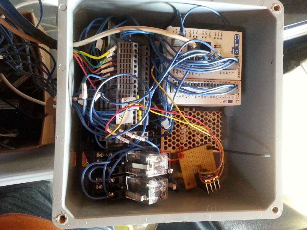
What is in the picture?
The PLC mounted on a din rail that is screwed through the back
of the box
To the right is the perf metal housing for the 12 volt to 24
volt DC inverter power supply. I think it can output about 1 amp
at 24 volts which is plenty to power the PLC and the two relays
and drive the PLC inputs.
The little perf board wire tied to the 12 volt to 24 VDC power
supply is a 5 volt regulator chip since I needed 5 volts to
power a RS232 to RS485 converter which is tucked under the
terminal strip. I think I wrapped the converter with
electrical tape to prevent shorts. The converter is used to
adapt the flux gate compass to the RS485 serial ports on the
bottom of the PLC. The bottom serial port on the PLC is used to
communicate with the LCD display that serves as a
tuning/setup/display device for the autopilot.
The two relays are used to drive the electric actuator. They are
easily replaceable since they are socketed.
The current incarnation uses an Automation Direct PLC which is very inexpensive as PLCs go and the software to program it is free.
The PLC used in this project was this one:
This plc has 4 - 24 VDC inputs and 4 - 24 VDC outputs. It also has two analog inputs and two analog outputs. The project was started before analog I/O cards were availabe for the Click family of PLCs. I also used a add on card for the PLC to gain additional inputs.
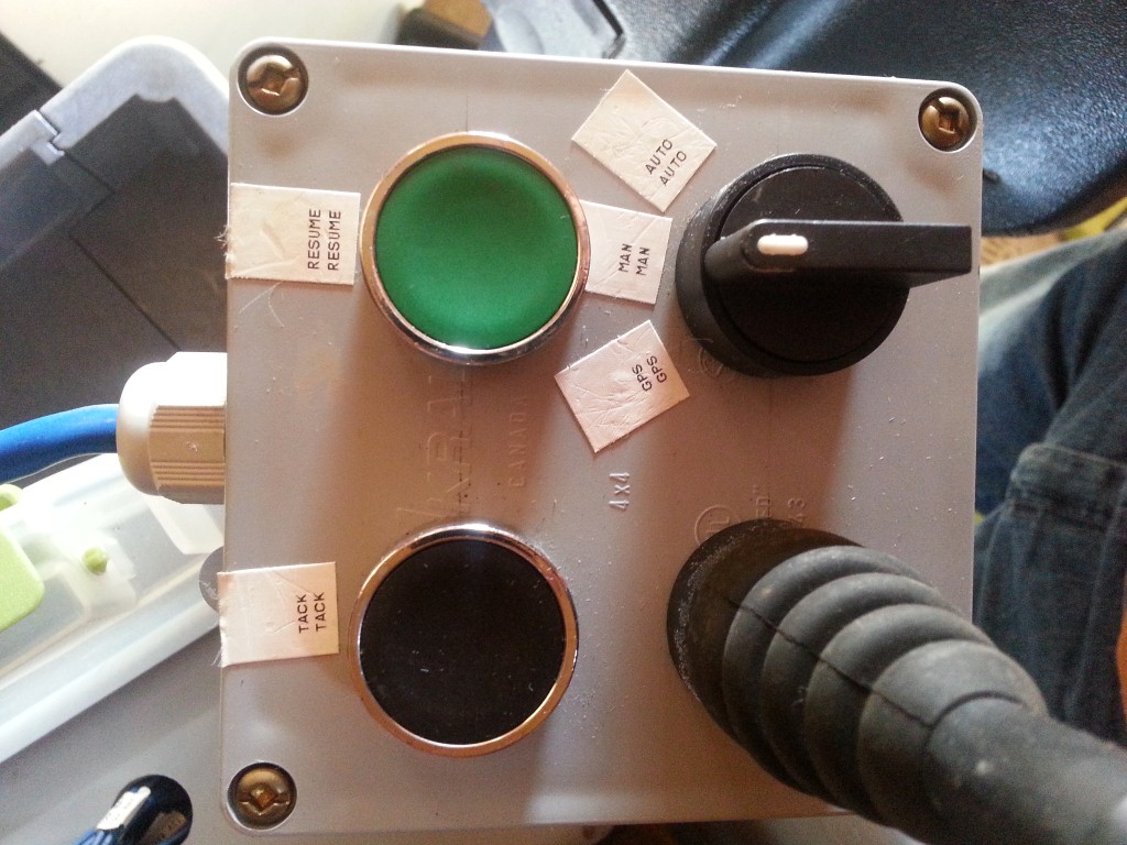
The additional inputs were used on a cabled waterproof pendant
which has a joystick and two buttons on it. A resume button and
a tack button.
The joystick is nice since if you are in Man mode you can steer
the boat with the joystick. Pretty nice if you have to steer but
want to plant your butt in the corner on a pillow for comfort.
Here is a picture of the pendant:
I also used a display unit to show the compass heading, deviation from desired heading, and tuning parameters, and mode settings. The display is a standard Automation Direct display which communicates with the PLC via a cable that looks like a phone cable, but is not.
This is the screen that was used.
http://www.automationdirect.com/adc/Shopping/Catalog/Operator_Interfaces/C-more_Micro-Graphic_Panels/3_inch_Panels_-a-_Accessories/EA1-S3MLW-N
Here is a picture of the actuator I used. This is a 12" stroke model and I used the available end fittings. This was purchased from Surplus Center in Nebraska. http://www.surpluscenter.com/
The actuator has a built in potentiometer that is used as a rudder position feedback device to the autopilot control.
http://www.surpluscenter.com/Brands/I-E-I/11-81-STROKE-110-LB-12-VDC-LINEAR-ACTUATOR-5-1577-12.axd
Here is a link to the PLC program.
Here is a link to the Screen/display program.
Here are wiring diagrams. I just realized that these diagrams are incomplete. I will update them.
The compass I used was a military surplus fluxgate compass purchased off Ebay for about $100. It is in a nice cast aluminum watertight box and it works very well. But since then newer compass chips have come out for less money and they work just as well. The CMPS10 chip is a good compass and I have tested it.
http://www.robot-electronics.co.uk/htm/cmps10doc.htm
However the CMPS10 has been discontinued and the replacement is the CMPS11 which I have not yet tested but it looks good despite the price increase from the CMPS10.
http://www.robotshop.com/en/tilt-compensated-magnetic-compass-cmps11.html
What would I do differently?
The Automation Direct screen is nice in that it is viewable in daylight. And it is nice to be able to tune the autopilot with the little screen. However the screen is really not required. Newer PLCs are now being sold that have built in web servers. If I am going to use a Tablet for navigation at the helm, then pulling up a webpage on the tablet to tweak the PLC autopilot controller makes a lot of sense. It also cuts about $150 out of the cost of the system.
When I first selected this PLC, Automation Direct did not have analog I/O cards, they only had PLCs with onboard Analog I/O. Also, I thought it would be important to be able to tie the navigation computer to the autopilot so the navigation computer can control the autopilot. With a Nav computer link, a compass link, and a screen link to the PLC, three serial ports are required. In hindsight, I think a Navigation computer link is really not required and may not even be desirable. Sailboats do not move fast. There is plenty of time to think about the desired heading for the autopilot.
When sailing close to the wind, having a wind indicator so the autopilot can sail to the wind direction would be a great advantage. So a second analog input would be desirable for a analog based wind indicator.
With these things in mind, a different PLC could be used. I'm thinking that the Siemens S7-1212 or 1214 would be a very good fit. That PLC has a built in webserver. Tie the PLC to a small Wireless AP for communication to a Tablet and that simplifies the hardware further and gets rid of some wires and it eliminates the need for a dedicated screen/MMI for the PLC.
If you make any improvement to this design please let me know and I will post them on this blog.
Happy Autopiloting ! :-)
Licensing stuff:
I grant this software/design a GPL3 open source license.
PLC based Autopilot design Copyright (C) 2015 Dave Cole This program is free software: you can redistribute it and/or modify it under the terms of the GNU General Public License as published by the Free Software Foundation, version 3 of the License. This program is distributed in the hope that it will be useful, but WITHOUT ANY WARRANTY; without even the implied warranty of MERCHANTABILITY or FITNESS FOR A PARTICULAR PURPOSE. See the GNU General Public License for more details. You should have received a copy of the GNU General Public License along with this program. If not, see http://www.gnu.org/licenses/